Although the state highway commission was founded in 1914, it was not until 1919 that a set of standardized bridge designs came into widespread use in the state. Before this time, county and city governments dealt with the representatives of the various bridge companies doing business at the time, and with rare exception, used the designs drawn by the engineers of those companies. However, widespread use of automobiles and trucks led to a "good roads movement" and an attendant demand for bridge structures of better quality than the light-weight "tin bridges" supplied by many bridge manufactures. Thus, by the 1920's, many bridges built in Oklahoma by even the oldest established makers were being built using or conforming to designs and design standards drawn by the state highway engineer's office.
Because of the varying geographical conditions the state roads have had to cope with, a variety of different standard designs were drawn up. For the truss type, the only kind being considered here, designs for lengths from 60 feet to 240 feet were drawn up. Although designs were standardized considerably from the bridges we've seen, variations in a particular type were often made, but in limited manners, such as panel lengths and widths of deck.
We will now look at the different types and then consider the evolution of a popular design as the highways and traffic matured.
Why did they build truss bridges then, and not now?
Simple: economics. It the era that truss bridges were built, labor was much cheaper that it is today, and the cost for the steel and transportation was higher, relatively. Although a truss bridge required much labor to fabricate and erect, it was efficient in use of steel, and because it could be transported to the site from the shop unassembled in many small pieces made it economic to build. An additional factor to consider was the relatively small sizes of available of structural steel shapes being rolled in the mills at the time. Trusses made it possible to economically and effectively utilize the many small angles, channels, and I's effectively.
Contrast this to today's conditions were labor is much more expensive. Beam bridges are now preferred. Although they require much more material, by weight, in steel or concrete, and the shop fabricated parts are much larger, bulkier units, there are fewer components to fabricate and erect thus requiring substantially less labor to construct. It is now possible to get a wide flange beam three to five feet deep or more capable of spanning 100 feet.
Since the author has not had access to records other than dates of construction of the bridges used for examples, much of what will be presented here has been taken from direct observation of the structures. In the book Spans of Time, Joseph King mentions a few bridge types not considered here, simply because not enough examples have been seen to make a comfortable confirmation that they were a 'standard' type.
Additionally, since many non-truss spans were often built as approaches to larger truss mainspans, details of non-truss spans are treated in the last portions of this document.
For structures with short spans, engineers designed what were often called the low truss, though now universally referred to as the pony truss. A pony truss consists of two main trusses for carrying the vertical loads connected together in the plane of the lower cord by a third truss, the lower lateral truss, for carrying horizontal wind loads. The lower lateral truss consists of tension diagonals and the cross beams of the flooring system for compression members. It is from these floor beams that the deck and live loads are supported.
This niche was usually filled by the 4-panel riveted Pratt design (sometimes called a Warren with verticals, but the geometry of the truss is clearly of the Pratt family). Examples found date from 1919 to the 1940's and are almost always either 60 feet, with 15-foot panels, or 80 feet with 20 foot panels. Stand alone spans can often be found, but more typically they were installed as approach spans for larger through trusses. Construction details can vary from bridge to bridge, the most variation being the construction of built up members.
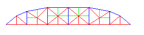
Above left, Oklahoma riveted Pratt pony truss. Blue members are in compression, red are in tension. Right, an 80-foot example built in 1930.
In this range the design of choice was the Parker modification of the Pratt design. The idea of a Pratt truss with a curved top cord was patented (US No. 100,185) by Charles H. Parker, of Boston, Mass., in 1870. By the time truss bridge building was underway in Oklahoma, the curved top cord had given way to the straight-segmented top cord we are familiar with today. As the smallest Parker trusses in Oklahoma, these pony trusses are 5 panels in length, and the two most common lengths by far were 80 and 100 feet, with most of the earlier examples being built at 60, 80, and occasionally 90 feet in length. It was common later on as bridges became wider to use the 60-foot length for approach spans in place of the 4-panel design discussed above. A very popular method for using this design was to string them together in series to make long bridges. The earliest example surviving of a bridge using this type dates to 1919 and consists of 8 spans. The largest bridge built from these spans was constructed in 1933 and utilized 38. Details in this design vary much more uniformly than in the pervious design, these variations being linked more the year the span(s) were constructed. Earlier examples use built-up members in the webs and lattice or channel type railings, one has been found with rolled 'I' sections for web members and batten plates in the upper chords instead of lacing; while the later examples use W (wide flange I shapes without tapered flanges) shapes for web members and W shapes for guard railings. This type was built until the end of Oklahoma new truss fabrication in the 1960's.


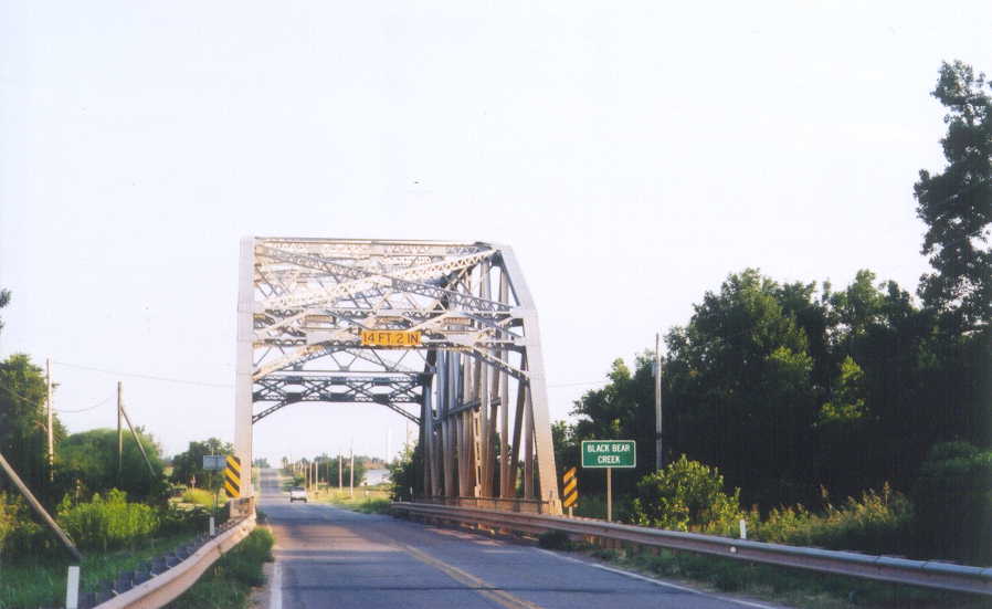
Oklahoma riveted Parker pony truss (left) and a photograph (right) of a typical example built in 1946.
A much less common variation on the 5 panel 80-100 design was this 6 panel camelback pony truss suitable for lengths up to 120 feet. Originally, the term camelback was used for all Parker-type Pratt trusses, but today camelback is reserved for Parker trusses with 5 slopes (including the endposts) to the top cord. In this document, I apply the term camelback to Parker trusses with 5 slopes, but more than 5 panels. Several examples have been documented in this type, most dating to the 1930's, with the earlier ones having built-up members and the later ones having wide-flange web members.


The 6-panel riveted camelback pony (left) and a photograph (right) of an example.
For longer spans, engineers universally favored the high- or through truss bridge. These bridges have additional steelwork connecting the two trusses together in the plane of the upper chords known as the upper lateral truss. The upper lateral truss consists of sway bracing, compression struts, tension diagonals, and a portal frame designed to carry horizontal wind loads to the abutments and piers, as opposed to the main trusses, which carry the vertical loads. The portal frame is a rigid framework built in the plane of the endposts and is designed to transfer the loads from the upper lateral truss through the endposts to the bottom ends of the bridge. In this section, we will look at the various through-truss designs that have been used in Oklahoma and then we will consider the different portal designs, as they are just as numerous and varied as the trusses themselves.
For this service, the state engineer's office designed a very adaptable 6-panel modified Pratt design. These were always built with riveted connections and their widespread construction seems to have only lasted one decade, 1921-1930, as few examples are known that have a later date. However, for spans of 120 feet built after 1930, the modified Camelback used seems to have been based directly off the modified Pratt, the extra depth of the Camelback design being an asset to a heavier, wider bridge of later design.


Above left, the modified Pratt truss. The green members are "nominal" members that do not normally carry loads, but stiffen the vertical blue members. This allowed designers to use a much smaller section, while gaining some strength. The photo at right shows one of the oldest of this type built, and also the shortest of this type built. At only 96 feet, it is an early example (1921) of an all-riveted standard design in Oklahoma, and is the shortest standard through bridge in the state. This example is the only one of this type with a simple "A frame" portal.
A rare variation on the above design is the 120-foot Camelback.


Above left, the 120 foot modified through Camelback, and right, a rare two span example of the type.
For spans longer than 120 but under 140 feet, 7-panel designs were used. Early examples were pin-connected Pratt spans, while later spans are modified Parker types. Eventually, K-type spans fixed at 140 feet were used.
 |
 |
| Above, schematic diagram of the 7 panels state standard design, without the horizontal center strut. | Above, the seven panel through Pratt with horizontal strut in center panel. The strut is a nominal members that serves to brace the blue (compression) members. |
 |
 |
| Above, a riveted example of a 140-foot 7-panel span without the horizontal strut. Although an example has not yet been found, it is less likely to find a pin connected example of this design. This example dates to 1928. | Above, an example of a combination pin-connected and riveted 7-panel standard through span. For larger (7 to 10 panels) spans, the early state standard designs were usually hybrid pinned-riveted spans, as this was a transitional era in bridge building in which the pin connected spans were falling out of favor. The strut used in this design allowed much smaller compression members to be be used, as the photo shows, the braced members are much smaller in size than the non-braced ones. Compare this to bridge in the photo left. This example is the 1921 Dover Bridge. |
As demands for higher weight carrying capacity increased, the through Pratt design fell out of favor, it being replaced by the more efficient Parker variant. However, we have not yet seen a built example of an unmodified 7-panel Parker through truss, so only the modified Parker will be considered. The modified Parker was a step between the Pratt spans considered above and the later, more efficient K-truss designs that followed later.


Above left, diagram of the 7-panel modified Parker truss. Members in green are nominal members that serve to stiffen the vertical blue members. Above right, a 1925 example of the 7-panel design. This example consists of three spans, each 140 feet in length. The nominal members allowed designers to use smaller, and hence lighter vertical compression members. This was important because steel was priced per pound.


Above left, the 7-panel K-truss. This arrangement of members was more efficient than the modified Parker design because it eliminated the nominal members while still stiffening the vertical compression members. Later versions of this design do not have the horizontal strut in the middle panel. The photograph, right, is a 1933 example of this type. This type was build until the end of the truss bridge era in Oklahoma and is the shortest of the Oklahoma K-truss designs.
These are the most prolific type of truss in the state, and the varied. Early versions can be found in riveted, pinned, and combination connections, Pratt or Parker design. Later versions are highly standardized with most of the variation being in portals and decks.


Above, the 8-panel Pratt truss. Like so many of the other designs, this one has the horizontal nominal strut in the middle panels. The photo is an example dating to the early 1920's using combination pinned-riveted connections and a simple A-frame portal.
When extra strength was required, the Parker variation was used, and it was this that evolved into the modern K-truss design used all over the state.
 |
At left are the four most common designs of 8-panel Parker and
K-truss. Figure A shows the earliest and most common of the Parker
variation. In standard fashion, the horizontal nominal strut is used to
reduce the size of the longest verticals. This design was the
cornerstone of all those that followed. Figure B shows the most common arrangement of the 8-panel Modified Parker design. Slight variations do exist in the orientation of the diagonal portion of the angled nominal members, much like the arrangement in the 7-panel modified Parker shown above. Use of the extra nominal members allowed a further reduction in size and weight of the vertical members. The next step in this progression is shown in figure C. Here we see the removal of the nominal members in favor of active members arranged in a "K", allowing a greater efficiency in the use of materials. However, in this design, the center "X"s with struts still remain. This was resolved by the mid 1930's with figure D, with "K"s in all appropriate panels. It is this final form that was used until the 1960's, when truss building activity largely stopped. Most variations in the final design center around the portal and the width of the bridge. |
| An example of the bridge shown diagrammatically at A is pictured at the right. It is a 1921 example built with A-frame portals. Although widespread use of this design for important routes was discontinued by 1931, a two-span example has been found found on an Osage County road with a 1948 date plaque. |
 |
| At right is an example of the modified Parker shown at B. This example was built in 1931 and features more modern modified A-frame portals. Heavier and wider bridges were built using the modified Parker design in the 1920's. |
 |
| Also built in 1931, this bridge features the K-pattern shown at C. This modification allowed greater economy of steel. Otherwise, this bridge, in construction detail and size, is identical to the one shown above. The portal knee-braces in this example, however, have been removed. |
 |
| By 1935, when this bridge was built, D in the diagrams, the K was used in all applicable panels and the size of the members was increased to cope with the even greater weights required. This design was used until 1960, the only modifications made involved those related to deck widths and portal design. |
 |
In this very rare category are 3 types: Parker, riveted or combination connections, modified riveted Parker, and K-truss. Examples of all three types, with riveted connections in all cases, have been recorded, and an example of a combination connected Parker has been recorded. Like most of the other type considered, early examples date to the 1920's, with later examples dating to the 1960's
 |
 |
Above, a 189-foot long 9-panel riveted Parker span. This example does not have the nominal strut in the center panel. This example was built in 1928.
 |
 |
Also dating to 1928, the example above shows the 9-panel modified Parker truss. The span length here is also 189 feet.
 |
 |
Above, like all the other types, this one eventually evolved to use the K-truss pattern of web members, as it does away with the number of nominal struts and ties. The example at right, dates to 1960.
This category, reserved for the largest spans, is, surprisingly, the least varied. Only two types have been noted: Parker spans, either riveted, or pinned and riveted, and a combination of Parker and K truss. As we saw in the 8-panel design, the middle two panels were eventually resolved with the K arrangement, however, the middle panels of 10-panel bridges retained the tie/counter tie 'X' arrangement of the Parker truss. Three good examples of early practice stand out for this type; the 1919 Calvin bridge, used 190-foot long combination pinned and riveted spans, the 1923 Newcastle bridge, used 210-foot spans identical to the Calvin Bridge, and the 1924 Arkansas River Bridge north of Muskogee, the earliest surviving all-riveted example, built 210 feet in length. An all-riveted span has been recorded dating to 1928 that is of interest because it lacks the horizontal struts in the center panels all the other examples have. In 1931, the first K-truss version of this type was built, and the examples photographed show a variety of details, many of which correspond to year of construction, deck width, and intended duty. It is not uncommon to find upper chords double-laced on many of the heavier or later examples.
 |
 |
Above left, for spans from 190 to 210 feet, The Parker truss was used extensively from 1919 to circa 1930. The example on the left shows a riveted example from 1927, though this type was being built all-riveted as early as 1922. Pictured below is a combined pinned and riveted bridge from 1923. Like so many of the previous types, most were built with a nominal strut in the center panels, though one all-riveted example without the strut from 1928 has been recorded.

Unlike many of the previous examples, no example of this design has been recorded in the modified Parker form. This design seems to have gone straight to the K-arrangement of web members.
 |
 |
Above, the Oklahoma K-truss, a combined Parker-K truss design. Recorded early examples date to 1931, late examples in the early 1960's. This type was universally built in 210-foot lengths with variations occurring in guard rails, portal layout, deck widths, and overall weight of construction. The example pictured here dates to 1949.
Two examples are known to the author in this category, the demolished Asher bridge over the South Canadian River on Highway 18, and the demolished Will Rogers bridge over the Neosho River on Route 66 at Miami.
 |
|
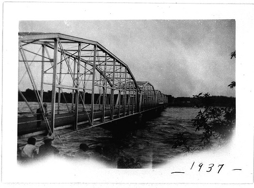
Above, 12 panel Pennsylvania or Petit truss. Photo of the Asher Bridge taken in 1937 from http://asheroklahoma.info. This bridge was built in 1921, and served State Highway 18 from 1924 to 1964. Six Pennsylvania spans were used in this bridge. The Pennsylvania truss was developed as a variation of the Parker truss in the late 19th century by engineers of the Pennsylvania Railroad. In the Pennsylvania truss, additional ties and struts are added in a fashion similar to the Modified Parker trusses considered earlier. However, a further step is taken in which the panels are subdivided into half-panels. The flooring system and lower cord can be thought of as having 12 panels, yet in examining the truss, if the green nominal members are omitted, there are really only eight panels. If one then goes on and realizes that the red tension hip verticals, and half-length tension verticals are there just for the floor system, and omit those, the number of panels decreases to six. To our knowledge, this design was the only Pennsylvania truss in the OSHC library of standard plan truss bridges. It is still unknown how many other structures were built with the state-standard Pennsylvania truss.
 |
 |
Above, the 12-panel K-truss. Photo of the Will Rogers bridge from http://schehrer2.homestead.com/miami_6.html . Note the the nominal strut in the middle two panels. It is not known whether this bridge type was ever duplicated, or if it was a single, land-mark example. As shown by the previous example, the OSHC had previous standards for trusses with 12 panels. This bridge was built in 1937 and demolished in 1996.
Throughout the years, several different portal designs were used. Here is a rough guide to the different types based on what we've observed.
Two different portal designs were used during this period, the simple A-frame type, and the more sophisticated 4-panel quadrangular Warren type with curved (quarter circle) knee braces. In general, both of these types were nearly identical to portals used on many of the company-designed bridges.
 |
 |
| Above, the A-frame portal. Each member is made up of paired angles. | The Quadrangular Warren portal. Here, only the upper and lower struts, as well as the knee-braces are made of paired angles. The diagonals are single angles. |
Note that in both examples the intermediate sway braces are nearly identical.
In the early 1930's a more modern portal came into standard use. It combined the 4-panel quadrangular Warren type with the A-frame type to produce basically a quadrangular Warren portal with straight knee-braces. However, unlike the earlier portals, these were built up to be the same depth as the endposts using batten plates and lacing. Since most of the earlier bridges were narrow, 4 panels worked fine, but bridges were getting wider and soon the design was revised to 6 panels. Indeed, the 4-panel version of this portal seems to have only existed for one year-1931, and has only been found on a few 8-panel structures.
 |
 |
| Above, a typical early version (1931) of this portal with 4 panels. This example is unique, the knees are still present. | In this picture, you can see the evidence that a knee-brace was present. The wide plate interrupting the lacing on the endpost would have been the gusset plate where the lower end of the knee attached. |
| Below, a close-up of the knee and the general portal construction with the batten plates and lacing. | Below, a typical example of a modified portal, as seen from outside the bridge. You can still see the gusset plate riveted to the cover plate on the endposts. This example also dates from 1931. |
 |
 |
Sometime around 1935, the Quadrangular Warren portal stopped being built with kneebraces. This required very little structural change to the portal design, apparently the portal was stiff enough to be built without them and they were a clearance issue. The revision was carried out retroactively on many earlier bridges, leaving gusset plates and cut marks as evidence. Later examples on wide bridges still using this portal will have 7 panels. Most of the recorded examples of this portal on bridges built after 1940 have been the 10-panel Parker-K truss spans.
 |
 |
| Above, a 1939 example of the revised portal, with 6 panels. | Above, probably one of the last examples of the Quadrangular Warren portal, built in 1950 with 7 panels. |
Sometime in the 1940's a plain Warren without verticals design started to be used for the portal frame. This design was usually 4 or sometimes 5 panels and is typically found on bridges built with wide curbs. Two K-truss structures, however, have been recorded with 18-foot wide decks built in 1948 and 1954 using this portal with only 2 panels. These are spans built to standard specification for bridges with narrow decks. Most of the recorded examples of this portal have been found on 8-panel K-truss spans built after 1940.
 |
|
| Above, a 1945 example of the Warren portal. | Above, a 1940 example. Note the extra depth of the portal. |
This was the last portal design to be used and is generally found on bridges built after 1954. It is a Warren with verticals design and is six panels. Recorded examples have been found only on 10-panel Parker-K spans.

Above, a 1954 example of the Warren with verticals portal.
Steel Bridge Rails
-There were two types used throughout this period-channel rails (until c1930) and lattice rails.
Channel type-The channel rails varied very little and consisted of two horizontal rows of structural rolled channel mounted with the flanges facing in. Bolts or rivets can be found at the mounting points. They were mounted with angles or tees to the web members and with stanchions at the ends of the span, These stanchions generally consisted of a vertical angle and a diagonal angle brace. Occasionally, a vertical angle will be found at the mid point of each panel connecting the channels to the deck.
 |
 |
| Above, a typical early example of the channel rail from 1921. Note in this example, the railing continues onto the approach span. | Above, a rare undamaged example of the end stanchion once found on every bridge. |
Lattice type-These varied to a greater degree than the simple channel rails, with more variation occurring in the earlier years. The lattice rails consisted of two rows of horizontally mounted tees (or more rarely angles) connected together by crisscrossing flat bars or angles. The mounting methods for this type were so nearly identical to the channel rails considered earlier that further explanation is not required. Three patterns of lattice rail have been recorded, with one of the patterns being found only in Grant County on two 1919 structures. This type consist of lattice bars that crosses 3 other bars between end points. Three examples have been recorded of the second pattern. Two of these examples happened to be built by The Vincennes Bridge Co., while the third has no record of its builder. This pattern uses angles instead of bars to construct the lattice. Each angle crosses 2 other angles between endpoints. All other bridges use basically the same patter of lattice bars crossing only one other bar between endpoints.
 |
 |
| Above, one of the 1919 Grant Co. examples with the triple-cross lattice | |
 |
|
| Above, an example of the more common lattice railing as used on Oklahoma's bridges from 1919 to 1932. In this example paired angles are used to construct the top and bottom rail, though it is more common to find a tee section used. | Above, an example of the angle-lattice rail on one of the Vincennes Bridge Co. built bridges. This example dates to 1922, the other two both date to 1924. |
Starting in 1932, a revision in the end construction of all bridge types resulted in changes to the stanchion construction. This coincided with the introduction of a new railing design that replaced the lattice type on all new bridges. By 1933, virtually all truss structures were using this new rail. This rail consisted of two horizontal rows of H-shaped wide-flange steel sections mounted directly to the vertical members or endposts with bolts or rivets. No intermediate bracket was used, though shims were often used. Since the sections were mounted just as you see the letter H on this page, drain holes were drilled at regular intervals in the web to prevent water standing.
 |
 |
| Above, typical stanchion that was used with lattice (and channel) type railings to c1932. | In c1932, the stanchion construction was revised as shown above. A few 1931 and 1932 examples with lattice type railings have been found with this stanchion. |
| Note that in both of these illustrations the stanchion revisions coincides with a revision in the attaching method of the end floor beams. In both illustrations, a pony span is on the left, and a through span is on the right. | |
|
|
|
| Above, detail of typical rail as used from c1932 to c1960. | |
Concrete rails
Circa 1919 to c1950
-These were what we have to come to call the "fence" design; two horizontal precast concrete rails supported at regular intervals by poured-in-place concrete posts, normally spaced no more than 10 feet apart. These posts are typically greater in width (18") at the ends of the bridge or span, with narrow posts (15") used in intermediate positions. Early (to circa 1940) posts typically have a cast-in recessed panel, much like the panels on a wood door, while later examples (c1940 to c1950) have the "Deco bars" pattern as is illustrated below.
 |
 |
 |
 |
| Above, typical end (left) and intermediate (right) "Panel" type used up until circa 1940. | Above, typical end (left) and intermediate (right) "Deco Bars" style used after c1940. Note that the precast concrete rails are much heaver than on the earlier style. | ||
Concrete Rails After circa 1950
Around 1950, the concrete fence rail was revised to use only one horizontal row, set flush with the inside face of the vertical posts. Narrow posts were no longer used for the intermediate positions, but the posts did retain the "Deco Bars" design. This design was used into the late 1950's or early 1960's, when a steel rail design replaced the concrete rails completely.
 |
 |
| Above, a 1951 bridge using the new rail type on its approaches. |
 |
| Top right, view of the rail and posts. | |
| Bottom right, rail as viewed from above showing flush face on traffic side. This was probably considered a great advance in safety at the time. | |
| Note in all the example pictures the wide curb. This type was predominantly used with this detail. |
From Circa 1960
Starting about circa 1960, concrete railings on non-truss span were replaced with a steel railing. With this change came a slight reshaping to the curb. The vertical surfaces of the curbs used in conjunction with this detail will have a slight batter to them, angling away from the centerline of the bridge.
| Right, steel rail used on non-truss span after about 1960. It consists of a horizontal rail made up of a wide channel supported by vertical posts made from wide-flange steel "H"'s. The horizontal channel rail was always installed with the flanges facing out away from the deck, at about the same height as the concrete rail in the previous design standard. |
 |
 |
Left, an example of this type railing used on an approach span for a truss bridge. |
This was the last guard rail detail used when the truss building era ended in 1965. A large through truss bridge built in Choctaw County in 1965 may have been the last new highway truss bridge in Oklahoma. It's approach spans utilized this guard rail detail.